
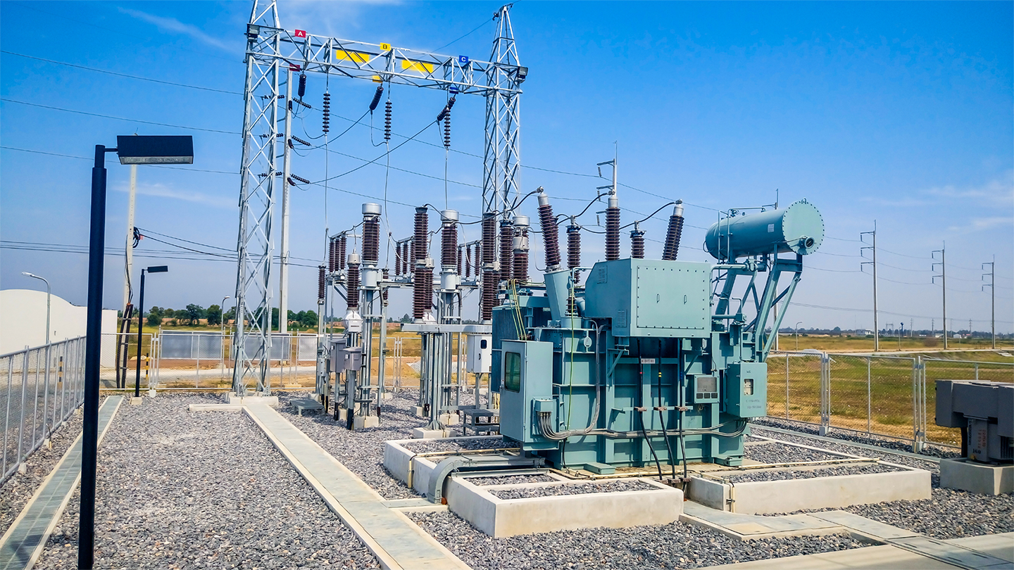
Modern power grids rely on a multi-stage voltage hierarchy to move electricity from distant generating plants to homes, hospitals, and factories without losing massive amounts of energy as heat. Within this hierarchy, 33kV and 11kV substations form the indispensable middle and final links of the medium-voltage distribution chain (IJERT Study). While bulk transmission lines carry electricity across hundreds of kilometers at 132kV, 220kV, or 400kV, it is the 33kV Primary Distribution Network and the 11kV Secondary Distribution Network that step those dangerous voltages down, route power through cities and industrial estates, and feed the local transformers outside our buildings (Electrexia).
Whether you are an electrical engineering student, a utility technician, an industrial facility planner, or an energy enthusiast, understanding how 33kV and 11kV substations work—and how their components, ratings, and architectures differ—gives you a complete picture of how the modern power grid keeps the lights on (EEP Substation Basics).
Staged Voltage Reduction Minimizes Line Losses Across the Electrical Grid
Power plants typically generate electricity at medium voltages between 11kV and 25kV (Electrowa). If utilities attempted to push that power across a 200-kilometer line at generator voltage, the resulting current ($I$) would be enormous. Because resistive heating losses in conductors scale with the square of the current ($I^2R$), transmitting high current over long distances wastes vast amounts of electrical energy and requires impractically thick cables (Electrowa).
To solve this, utilities step the voltage up to 132kV or higher for long-distance bulk transfer, then step it down in carefully engineered stages as the power approaches load centers (EEP Substation Basics):
- Bulk High-Voltage Transmission (132kV and Above): Carries massive power blocks from generating stations to regional grid substations over long inter-city spans using steel lattice towers (Electrowa).
- Regional Sub-Transmission (66kV): Transfers power from major 132kV grid stations across medium distances (such as 50 to 80 kilometers) to regional utility hubs and heavy industrial estates (Electrowa).
- Primary Distribution (33kV): Receives power from 132kV or 66kV stations and serves as the regional distribution backbone, feeding medium-to-large industrial plants (steel mills, cement factories, chemical plants), urban zone substations, and commercial complexes (Electrexia).
- Secondary Distribution (11kV): Branches out from 33/11kV Substations into neighborhoods, commercial streets, campuses, and rural villages, delivering medium-voltage power directly to local distribution transformers (Electrowa).
- Low-Voltage Consumer Supply (400V / 230V): Steps down the 11kV supply at pole-mounted or pad-mounted distribution transformers to three-phase 400V/415V or single-phase 230V for household and commercial appliances (Delixi Electric).
33kV Substations Serve Regional and Industrial Loads While 11kV Substations Feed Local Consumers
Although both 33kV and 11kV systems fall under the medium-voltage distribution umbrella in many utility standards, they serve distinct geographic scales, load capacities, and customer profiles (Ryan Electric). A 33kV Grid Station acts like a major regional railway junction that organizes incoming bulk traffic and dispatches it along high-capacity corridors, whereas an 11kV Substation acts like a neighborhood transit hub that distributes power down individual streets (Electrexia).
| Technical Parameter | 33kV Substation (Primary Distribution) | 11kV Substation (Secondary Distribution) |
|---|---|---|
| Nominal Operating Voltage | 33,000 Volts (33kV) (Electrexia) | 11,000 Volts (11kV) (Electrowa) |
| Highest System Voltage ($V_m$) | 36kV (at 1.1 × nominal tolerance) (IJERT Study) | 12kV (at 1.1 × nominal tolerance) (IJERT Study) |
| Primary Grid Role | Regional power distribution and stepping down 132kV/66kV to 33kV or 33kV to 11kV (Electrexia) | Local neighborhood distribution and stepping down 11kV to 400V/230V (Delixi Electric) |
| Typical Coverage Area | Towns, industrial corridors, and multi-kilometer regional feeders (Electrowa) | Short-to-medium local radii across residential blocks and commercial streets (Electrowa) |
| Typical Transformer Ratings | 5 MVA, 10 MVA, 12.5 MVA, up to 16–63 MVA in primary stations (IJERT Study) | 25 kVA to 315 kVA (pole-mounted) and 500 kVA to 2,500 kVA (ground/indoor) (Delixi Electric) |
| Physical Construction | Predominantly foundation-mounted outdoor Air Insulated Switchgear (AIS) or urban indoor Gas Insulated Switchgear (GIS) (DipsLab) | Single-pole or H-pole mounted outdoors, pad-mounted kiosks, or indoor commercial rooms (NPC Electric) |
| Typical End Consumers | 11kV distribution substations, steel plants, textile mills, hospitals, and railway traction (SPKN India) | Apartment complexes, homes, schools, offices, small workshops, and irrigation pumps (Electrowa) |
| Insulation & Clearance Needs | Larger phase-to-phase and phase-to-earth air clearances; 70kV power-frequency withstand (IJERT Study) | Compact air clearances and smaller bushings; 28kV power-frequency withstand (IJERT Study) |
The 33/11kV Primary Distribution Substation Links Regional Feeders to Neighborhood Networks
The workhorse of utility distribution is the 33/11kV Substation, which receives incoming power at 33kV and steps it down to 11kV across multiple outgoing feeders (IJERT Study). Following the Single Line Diagram (SLD) from the incoming overhead gantry to the outgoing feeder cables reveals a carefully sequenced chain of protection, isolation, measurement, and transformation (Integrated Power & Engineering).
Power Flows Sequentially From Incoming 33kV Lines to Outgoing 11kV Feeders
- Incoming 33kV Overhead Feeders and Lightning Arresters: Power arrives via 33kV Aluminium Conductor Steel Reinforced (ACSR) overhead lines or Cross-Linked Polyethylene (XLPE) underground cables (Electrowa). Positioned immediately at the line entry are 33kV Lightning Arresters (surge arresters), which clamp dangerous voltage spikes from lightning strikes or switching surges and divert surge currents safely to earth before they can reach the transformer windings (Integrated Power & Engineering).
- Line Isolators and Instrument Transformers: Next in line is a 33kV Isolator (disconnector switch) with an earthing switch, followed by Current Transformers (CTs) and Potential Transformers (PTs) (SPKN India). The CTs and PTs scale high primary currents and voltages down to standardized secondary values (such as 1A/5A and 110V) for metering and protective relays (IJERT Study).
- 33kV Circuit Breaker and 33kV Busbar: The line passes through a 33kV Vacuum Circuit Breaker (VCB) or $SF_6$ breaker capable of interrupting heavy fault currents within milliseconds (IJERT Study). Where multiple incoming lines or transformers exist, a copper or aluminum 33kV Busbar with a bus coupler distributes power across bays so maintenance on one bay does not black out the entire station (IJERT Study).
- 33/11kV Power Transformer: The heart of the substation is the three-phase 33/11kV Step-Down Power Transformer (commonly rated at 5 MVA, 10 MVA, or 12.5 MVA) (IJERT Study). It typically uses a Dyn11 vector group—a Delta-connected 33kV primary winding that traps third-harmonic currents and a Star-connected 11kV secondary winding that provides a grounded neutral point (IJERT Study).
- 11kV Incomer Switchgear and Busbar Section: Secondary power leaves the transformer’s 11kV bushings via XLPE cables or bus ducts and enters the indoor 11kV Switchgear Room (Electrexia). After passing through 11kV lightning arresters, CTs, PTs, and the main 11kV incomer VCB, power energizes the segmented 11kV Busbar (IJERT Study).
- Capacitor Banks and Outgoing 11kV Feeders: Shunt Capacitor Banks connected to the 11kV bus supply reactive power locally to improve the power factor and stabilize bus voltage (Integrated Power & Engineering). Multiple outgoing 11kV Feeder VCB Panels then dispatch power to residential neighborhoods and commercial zones (Electrexia).
Primary and Secondary Substation Equipment Must Be Precisely Coordinated
Engineers divide substation hardware into primary equipment—the high-voltage machinery that directly carries, switches, or transforms power—and secondary equipment, which operates at low voltage in the background to monitor, protect, and control the primary side (Integrated Power & Engineering).
Primary Equipment Handles High-Voltage Transformation, Switching, and Surge Protection
- Power and Distribution Transformers: In a 33/11kV station, oil-immersed power transformers with ONAN (Oil Natural Air Natural) or ONAF (Oil Natural Air Forced) cooling systems and On-Load Tap Changers (OLTC) regulate secondary voltage within $\pm 5\%$ in $2.5\%$ steps even as feeder loads fluctuate (IJERT Study). Internal gas-operated Buchholz Relays, oil surge relays, and winding temperature indicators protect the tank against internal incipient faults (Electrexia).
- Circuit Breakers (VCB and SF6): Unlike fuses, a circuit breaker extinguishes high-voltage arcs safely under full load or short-circuit conditions and resets immediately for reclosing (Integrated Power & Engineering). Vacuum Circuit Breakers (VCBs) dominate both 11kV and 33kV distribution bays because they extinguish arcs inside sealed vacuum interrupters within 60 milliseconds (under 3 cycles at 50Hz) with minimal contact wear and zero toxic gas handling (IJERT Study).
- Isolators (Disconnector Switches): Because a circuit breaker’s interrupter chamber is enclosed, technicians cannot visually confirm that contacts have separated before starting maintenance (SPKN India). A Double Break (DB) or horizontal center-break isolator—built to IEC 62271-102 and IS 9921 standards—rotates its conducting blades to create a visible physical air gap (SPKN India). Because isolators lack arc-quenching chambers, they must never be opened or closed under load; operators always trip the circuit breaker first, then open the isolator, and finally close the integrated earthing switch (SPKN India).
- Instrument Transformers (CTs and PTs): Connected in series with the line, Current Transformers (CTs) step primary currents (such as 600A on the 33kV side or 1200A on the 11kV side) down to 1A or 5A (IJERT Study). Connected in parallel, Potential Transformers (PTs) step 33,000V or 11,000V down to 110V with dual accuracy classes (such as 0.2 for precision tariff metering and 3P for protective relaying) while galvanically isolating control panels from lethal voltages (IJERT Study).
- Metal Oxide Varistor (MOV) Lightning Arresters: Gapless zinc-oxide surge arresters remain non-conducting at normal operating voltages but become highly conductive within microseconds when an overvoltage wave hits, clamping the surge and returning to an insulating state once the transient passes (EEP Substation Basics).
Benchmark Equipment Ratings Illustrate the Engineering Gap Between 33kV and 11kV Bays
In a standard 12.5 MVA, 50Hz 33/11kV Substation design, the full-load current on the 33kV primary side is $218.6\text{ A}$ ($I_1 = \frac{12.5 \times 10^6}{\sqrt{3} \times 33 \times 10^3}$), whereas the full-load current on the 11kV secondary side triples to $656.0\text{ A}$ ($I_2 = \frac{12.5 \times 10^6}{\sqrt{3} \times 11 \times 10^3}$) (IJERT Study). Consequently, 33kV equipment requires higher dielectric insulation and voltage withstand margins, while 11kV transformer incomers must carry three times the continuous current (IJERT Study).
| Equipment Category | Technical Parameter | 33kV Side Specification | 11kV Side Specification |
|---|---|---|---|
| Lightning Arrester (MOV) | Rated Voltage / MCOV | 30kV Rated / 25kV MCOV (IJERT Study) | 9kV Rated / 8kV MCOV (IJERT Study) |
| Lightning Arrester (MOV) | Nominal Discharge Current | 10 kA (IJERT Study) | 5 kA (IJERT Study) |
| Potential Transformer (PT) | Transformation Ratio | $33\text{kV}/\sqrt{3}$ to $110\text{V}/\sqrt{3}$ (IJERT Study) | $11\text{kV}/\sqrt{3}$ to $110\text{V}/\sqrt{3}$ (IJERT Study) |
| Potential Transformer (PT) | Power-Frequency Withstand | 70 kV (50VA burden, Class 0.2/3P) (IJERT Study) | 28 kV (100VA burden, Class 0.2/3P) (IJERT Study) |
| Current Transformer (CT) | Multi-Core Current Ratio | 1200-600-150 / 1-1-1-1 A (30VA burden) (IJERT Study) | 100-1200 / 1-1-1-1 A (20VA burden) (IJERT Study) |
| Vacuum Circuit Breaker (VCB) | Short-Circuit Breaking / Making | 25 kA (1 sec) / 62.5 kAp; $\le 60\text{ ms}$ break (IJERT Study) | 25 kA (1 sec) / 62.5 kAp; $\le 60\text{ ms}$ break (IJERT Study) |
| Double Break Isolator | Short-Circuit Thermal / Peak | 25 kA (1 sec) / 62.5 kAp; Motor or Manual (IJERT Study) | 13.1 kA (1 sec) / 33 kAp; Manual operated (IJERT Study) |
Secondary Systems Provide Autonomous Fault Sensing, DC Trip Power, and Grounding
- Protective Relays and IEDs: Modern substations replace electromechanical relays with microprocessor-based Intelligent Electronic Devices (IEDs) or feeder terminals (EEP Substation Basics). Overcurrent, earth-fault, differential, and distance relays continuously evaluate CT and PT waveforms, balancing system availability against equipment protection so faults are isolated in milliseconds without nuisance tripping (EEP Substation Basics).
- Station Battery Bank and DC Auxiliary System: If a three-phase short circuit collapses the AC grid voltage, the substation cannot rely on AC power to trip its breakers (Integrated Power & Engineering). Dedicated 110V DC or 48V DC Battery Banks and float chargers power the relay panels, breaker trip coils, motorized isolators, and emergency lighting during total blackouts (Integrated Power & Engineering).
- Substation Earthing Grid: A buried mesh of copper or galvanized steel strips connected to deep earth electrodes bonds every transformer neutral, tank body, gantry column, and isolator frame to earth (Integrated Power & Engineering). Low earth grid resistance keeps step potential and touch potential within safe human limits during ground faults and guarantees sufficient fault current for earth-fault relays to trip rapidly (Electrexia).
Pole-Mounted 11kV and 33kV Distribution Substations Demand Integrated Package Sizing
When 11kV or 33kV overhead lines reach residential neighborhoods, rural farms, or small commercial sites, utilities step the voltage down to 400V/230V using Pole-Mounted Substations (Delixi Electric). Generally installed on a single pole for transformers up to 200 kVA and on an H-pole (double-pole) structure for capacities from 250 kVA up to 500 kVA, these compact installations follow a direct vertical power path (Delixi Electric):
- MV Overhead Tap and Surge Arresters: Three polymer-housed surge arresters tap off the overhead line via pin or post insulators (Delixi Electric). Bonding the arrester earth lead directly to the transformer tank eliminates lead-drop voltage stress across the winding insulation during lightning surges (Delixi Electric).
- Drop-Out (DO) Fuse Cutouts: Mounted below the arresters on galvanized cross-arms, three expulsion-type Drop-Out Fuse Cutouts (or Horn Gap fuses) provide both short-circuit overcurrent protection and a visible drop-down isolation point when the fuse element melts (Delixi Electric).
- Hermetically Sealed Distribution Transformer: Usually oil-immersed and Dyn11-connected with an off-circuit tap changer ($\pm 2 \times 2.5\%$), the transformer sits on hot-dip galvanized channels (Delixi Electric). Utilities increasingly evaluate amorphous alloy cores (such as S(B)H15 series) against conventional silicon steel cores (S11 series); because rural transformers remain energized 8,760 hours per year, amorphous cores cut continuous no-load core losses substantially and pay back their capital premium over the asset’s 25-year life (Delixi Electric).
- Bimetallic Connectors and LV Distribution Box: Where aluminum overhead jumpers meet copper transformer bushing studs, bimetallic lugs or parallel-groove clamps prevent galvanic corrosion and hot spots (Delixi Electric). On the secondary side, weatherproof LV cables feed a pole-mounted LV Distribution Box (Feeder Pillar) housing a main Molded Case Circuit Breaker (MCCB), Surge Protective Device (SPD), metering CTs, and outgoing MCBs, RCBOs, orHRC fuses (Delixi Electric).
High-Voltage Fuse Links Must Match Whether the Pole Operates at 11kV or 33kV
Every component rating in a pole-mounted substation cascades from the transformer’s kVA capacity ($I_{HV} = \frac{\text{kVA}}{\sqrt{3} \times \text{kV}}$ and $I_{LV@400V} \approx \text{kVA} \times 1.44$) (Delixi Electric). Because primary current at 33kV is one-third of the current at 11kV for the exact same kVA rating, reusing an 11kV fuse link schedule on a 33kV pole-mounted transformer leaves the unit virtually unprotected against secondary faults (Delixi Electric).
Site Constraints Dictate Choosing Between Indoor GIS and Outdoor AIS Architectures
When planning a new 11kV or 33kV substation, engineers must choose between Outdoor Air Insulated Switchgear (AIS) and Indoor Gas Insulated or Metal-Enclosed Switchgear (GIS) based on land cost, environmental pollution, fire safety, and future expansion (NPC Electric).
- Outdoor Air Insulated Substations (AIS): Rely on ambient atmospheric air to insulate open busbars, isolators, and bushings (Electrexia). Because air requires generous phase-to-phase clearances, outdoor yards require larger plots of land, making them ideal for rural distribution networks, solar and wind farms, mining sites, and peripheral industrial zones where land is affordable and future bay expansion is likely (NPC Electric). They pair naturally with oil-filled power transformers, which offer lower cost per MVA and superior heat dissipation for large capacities (NPC Electric).
- Indoor Metal-Enclosed and Gas Insulated Substations (GIS): Enclose live conductors inside metal cubicles or sealed chambers filled with insulating gas, shrinking the overall footprint for dense metropolitan central business districts, hospitals, airports, metro stations, and data centers (NPC Electric). Indoor 11kV and 33kV substations shield equipment from coastal salt fog, industrial dust, moisture ingress, and wildlife flashovers, while lowering noise emissions (NPC Electric). For indoor bays inside commercial buildings or hospitals, engineers specify Cast Resin (Dry-Type) Transformers (such as SC(B)10 F-class epoxy resin units) to eliminate flammable insulating oil and simplify fire suppression requirements (Delixi Electric).
| Design Factor | Indoor Substation (GIS / Metal-Enclosed) | Outdoor Substation (AIS / Foundation or Pole) |
|---|---|---|
| Land Footprint | Minimal; ideal for high-value urban real estate (NPC Electric) | Large; requires wide air-insulation clearances (NPC Electric) |
| Preferred Transformer | Cast Resin / Dry-Type (fire-resistant, oil-free) (NPC Electric) | Mineral Oil-Immersed (high MVA, superior cooling) (NPC Electric) |
| Environmental Protection | Shielded from rain, UV, coastal salt, and dust (NPC Electric) | Exposed; requires Pollution Level III/IV creepage ($\ge 25\text{ mm/kV}$) in coastal/industrial zones (SPKN India) |
| Capital vs. Maintenance Cost | Higher initial building/HVAC cost; lower ongoing cleaning (NPC Electric) | Lower civil construction cost; higher periodic insulator and contact maintenance (NPC Electric) |
| Typical Service Life | 30 to 50 years (NPC Electric) | 30 to 50 years (25–30 years for outdoor mechanical switches) (SPKN India) |
Proactive Maintenance and Troubleshooting Prevent Costly Feeder Outages
Field experience shows that most 33kV and 11kV substation failures stem not from manufacturing defects, but from deferred preventive maintenance or overlooked procurement details (Integrated Power & Engineering). Addressing the four most common failure modes keeps primary and secondary distribution networks resilient:
- DC Battery Bank Degradation: If station batteries lose capacity over time and are never load-tested, the DC voltage collapses the moment a fault occurs—leaving the protection relay unable to trip the 33kV or 11kV breaker and allowing catastrophic transformer damage (Integrated Power & Engineering). Routine battery impedance and discharge testing is mandatory (Integrated Power & Engineering).
- Rising Earth Grid Resistance: Soil drying and conductor corrosion gradually raise earthing resistance above the target threshold (typically $\le 10\text{ }\Omega$ for distribution poles and much lower for primary yards) (Delixi Electric). Annual earth-resistance testing and inspection of bolted or exothermic ground joints prevent dangerous touch potentials (Integrated Power & Engineering).
- Isolator Contact Oxidation and Misalignment: Outdoor 33kV and 11kV isolator blades exposed to monsoon humidity, dust, or industrial fumes develop contact oxidation that causes localized overheating (SPKN India). Specifying silver-plated copper contacts, hot-dip galvanized frames, and proper insulator creepage ($25\text{ mm/kV}$ or higher in polluted zones) alongside periodic lubrication prevents flashovers (SPKN India).
- Transformer Thermal Overload and Unbalanced Feeders: Rising oil temperature or low outgoing 11kV voltage typically points to cooling fan failure, low oil level, loose bushing lugs, or heavy phase unbalance across outgoing feeders (Electrexia). Thermographic infrared inspections of bimetallic joints, silica gel breather checks, and periodic feeder load balancing resolve these issues before insulation degrades (Delixi Electric).
Digital Substations and Renewable Integration Are Transforming 33kV and 11kV Grids
Today’s 33kV and 11kV substations are no longer passive, one-way step-down nodes (Electrexia). Utility-scale solar parks and wind farms frequently interconnect directly at the 33kV bus, while commercial rooftop solar arrays and electric vehicle (EV) fast-charging hubs connect at the 11kV level, creating bidirectional power flows that require directional overcurrent relays and automated voltage regulation (SPKN India).
At the same time, utilities are upgrading conventional hardwired relay rooms into Digital Substations equipped with SCADA (Supervisory Control and Data Acquisition), motorized isolators with remote position telemetry, IoT thermal and partial-discharge sensors, and AI-driven predictive maintenance (Electrexia). Together, these upgrades allow grid operators to pinpoint feeder faults, isolate damaged cable sections, and restore neighborhood power in seconds—ensuring that 33kV and 11kV substations remain the resilient backbone of modern electricity distribution (Electrowa).