
World-Class Transformer Engineering & Manufacturing
VOLTCORE Engineering Solutions manufactures robust 3-Phase Distribution and Power Transformers custom-engineered to client requirements and international standards including IEC, ANSI, BS, VDE, and BSTI.
Our transformers range in rating from 50 KVA to 5,000 KVA for 11/0.415 kV distribution networks and up to 18,000 KVA for 33/11 kV grid substations. As a consistent guarantee of the highest quality, our transformers are fabricated with high-permeability Cold Rolled Grain Oriented (CRGO) silicon steel laminations with step-lap mitered joints for minimal hysteresis and eddy-current core loss.
Our engineering team is closely affiliated with international professional bodies such as IEEE and ASME, continuously incorporating state-of-the-art power engineering developments. Quality control is executed at every single stage of production, and all units undergo exhaustive routine and type testing in our well-equipped high-voltage testing laboratory in compliance with IEC-76, BDS-1081, ANSI, and BSTI standards.
Voltcore Official Quality Policy & Assurance Pillars
Reliable Power
The Reliable Power: High dielectric stability, heavy-duty thermal endurance, and vacuum-treated mineral transformer oil.
Customer Priority
Customer-Centric Engineering: Fully tailored impedance, tapping ranges, dual LV/HV bushings, and custom enclosure dimensions.
In-Time Delivery
24/7 In-Time Delivery & Support: Emergency breakdown dispatch, testing, commissioning, and preventive maintenance contracts.
Continuous CRGO Lab Testing
Continuous CRGO Optimization: Precision step-lap core stacking, low contact erosion, and low-loss electrolytic copper windings.
Engineered Transformer Solutions: 11kV & 33kV
Whether stepping down 11kV utility feeds to 415V for industrial and commercial factories, or stepping down 33kV primary transmission lines to 11kV for utility substations, Voltcore delivers turnkey custom-engineered transformers.
11 / 0.415 kV 3-Phase Distribution Transformers
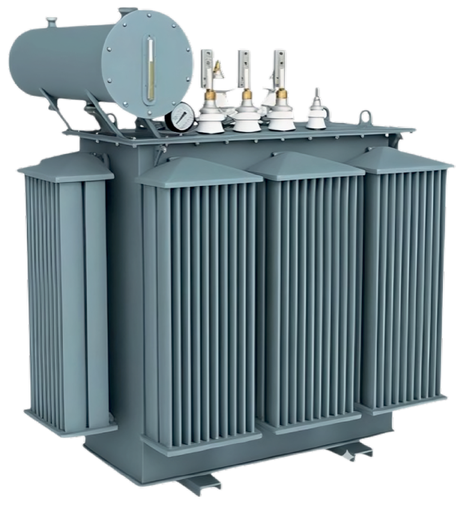
Engineered for commercial complexes, industrial plants, RMG factories, residential developments, and rural electrification networks. Built with corrugated cooling fins or pressed sheet radiators for superior natural oil circulation (ONAN).
Standard Design Features:
- Off-Circuit Tap Switch: ±2.5%, ±5% or ±2×2.5% to -7.5%
- Core: High-grade CRGO M4 / M5 prime silicon steel
- Windings: 99.9% electrolytic high-conductivity copper
- Tank: Hermetically sealed or conservator tank with silica gel breather
- Bushings: High-voltage porcelain DIN bushings with arc horns
- Protection: Oil level indicator, thermometer pocket, pressure relief device
33 / 11 kV 3-Phase Power Transformers
Heavy-duty substation power transformers engineered for utility grid step-down, industrial economic zones (EPZ), high-demand manufacturing plants, and utility-scale solar power grid interconnects. Designed to withstand severe lightning impulses, switching over-voltages, and system short-circuit stresses.
Standard Design Features:
- Tappings: Off-Circuit Tap Changer (OCTC) or On-Load Tap Changer (OLTC)
- Cooling: ONAN (Oil Natural Air Natural) / ONAF (Oil Natural Air Forced)
- Core: Step-lap CRGO with high stacking factor and low magnetizing current
- Protection: Buchholz double-float gas relay, magnetic oil gauge (MOG), WTI & OTI with alarm/trip contacts
- Impulse Withstand: Up to 170 kV BIL peak impulse insulation level
- Testing: Rigorous routine, temperature rise, and impulse testing according to IEC 60076
Transformer Design Parameters & Construction Standards
Electrical Specifications for Transformers
Full technical data table covering losses, efficiency at unity power factor, oil weight, total weight, overall dimensions, and impedance voltage.
| Sl. | Capacity (kVA) |
No Load Loss (W) |
Load Loss at 75°C (W) |
Efficiency @ Unity PF (%) |
Oil Wt (kg) |
Total Wt (kg) |
Length (cm) |
Width (cm) |
Height (cm) |
Impedance (%) |
|---|---|---|---|---|---|---|---|---|---|---|
| 01 | 50 KVA | 150 | 925 | 98.00% | 140 | 580 | 94 | 58 | 118 | 4.0% |
| 02 | 100 KVA | 245 | 1700 | 98.42% | 180 | 650 | 100 | 63 | 132 | 4.0% |
| 03 | 150 KVA | 320 | 2412 | 98.60% | 220 | 900 | 105 | 88 | 145 | 4.0% |
| 04 | 200 KVA | 435 | 2820 | 98.79% | 230 | 975 | 112 | 93 | 150 | 4.0% |
| 05 | 250 KVA | 520 | 3265 | 98.81% | 270 | 1100 | 113 | 95 | 158 | 4.0% |
| 06 | 315 KVA | 580 | 4500 | 98.89% | 350 | 1250 | 120 | 97 | 160 | 4.0% |
| 07 | 400 KVA | 722 | 5490 | 98.95% | 390 | 1450 | 123 | 98 | 162 | 4.0% |
| 08 | 500 KVA | 865 | 6275 | 99.00% | 425 | 1725 | 124 | 102 | 165 | 4.0% |
| 09 | 630 KVA | 920 | 7740 | 99.05% | 500 | 1970 | 136 | 103 | 170 | 4.5% |
| 10 | 750 KVA | 1150 | 8850 | 99.06% | 625 | 2250 | 155 | 112 | 185 | 5.0% |
| 11 | 800 KVA | 1300 | 9800 | 99.06% | 650 | 2575 | 170 | 113 | 200 | 5.0% |
| 12 | 1000 KVA | 1650 | 11600 | 99.08% | 800 | 2850 | 185 | 115 | 215 | 5.0% |
| 13 | 1250 KVA | 1820 | 12300 | 99.10% | 1000 | 3725 | 190 | 116 | 225 | 5.0% |
| 14 | 1600 KVA | 2200 | 14275 | 99.12% | 1200 | 4300 | 200 | 120 | 230 | 6.0% |
| 15 | 2000 KVA | 2650 | 16470 | 99.15% | 1450 | 4750 | 210 | 135 | 250 | 6.0% |
| 16 | 2500 KVA | 3140 | 19700 | 99.17% | 1800 | 5600 | 220 | 150 | 285 | 6.5% |
| 17 | 3000 KVA | 3420 | 22860 | 99.19% | 2050 | 6350 | 230 | 170 | 300 | 6.5% |
* Note on Specifications: All transformer specifications, loss levels, weights, and overall dimensions conform to official IEC-76 and BDS-1081 standards. Custom impedance voltages, special primary/secondary voltage combinations, and customized dimensional footprints can be engineered strictly as per customer requirements upon technical review.